
Dieline Workflow
 | Note: The Dieline module is an Enterprise Plan feature but can be added as an add-on for Growth Plan users. For more information on all ManageArtworks plans, click here. |
The Dieline module can be seamlessly integrated with workflows, making packaging development more efficient, flexible, and realistic.
- If you use the standalone Dieline module, you can create and preview dielines in 3D, but only as structural designs—without any artwork applied.
- To overlay artwork on a dieline and visualize how it looks in real life, you must link the dieline to the desired artwork through a workflow. Once the workflow is complete, the dieline with the applied artwork can be accessed from the Asset Library.
How do I link a dieline to a workflow or project?
 | Note: You can attach dieline only after project initiation. This article explains how to attach a dieline after project initiation. For details on creating a new project, see the Start a New Project section. This article focuses specifically on how to attach and manage a dieline within a project, and how to link it with packaging artwork. It does not provide step-by-step instructions for completing a workflow or project using a dieline. Before proceeding with the Dieline Workflow, it is recommended that you have a clear understanding of how workflows function in ManageArtworks. |
01. Access Project
- Sign in to your ManageArtworks account.
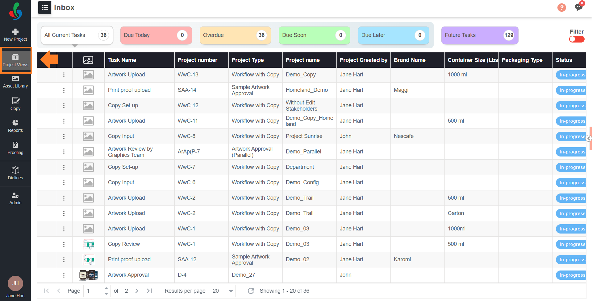
- Select the Project Views module.
- Select the target project/task.
02. Attach the Desired Dieline
| Note: Only one dieline can be linked to each component in a project. |
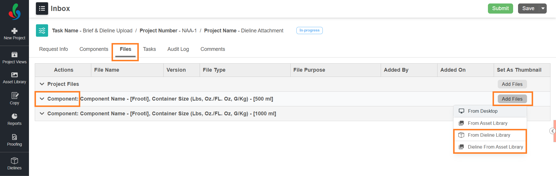
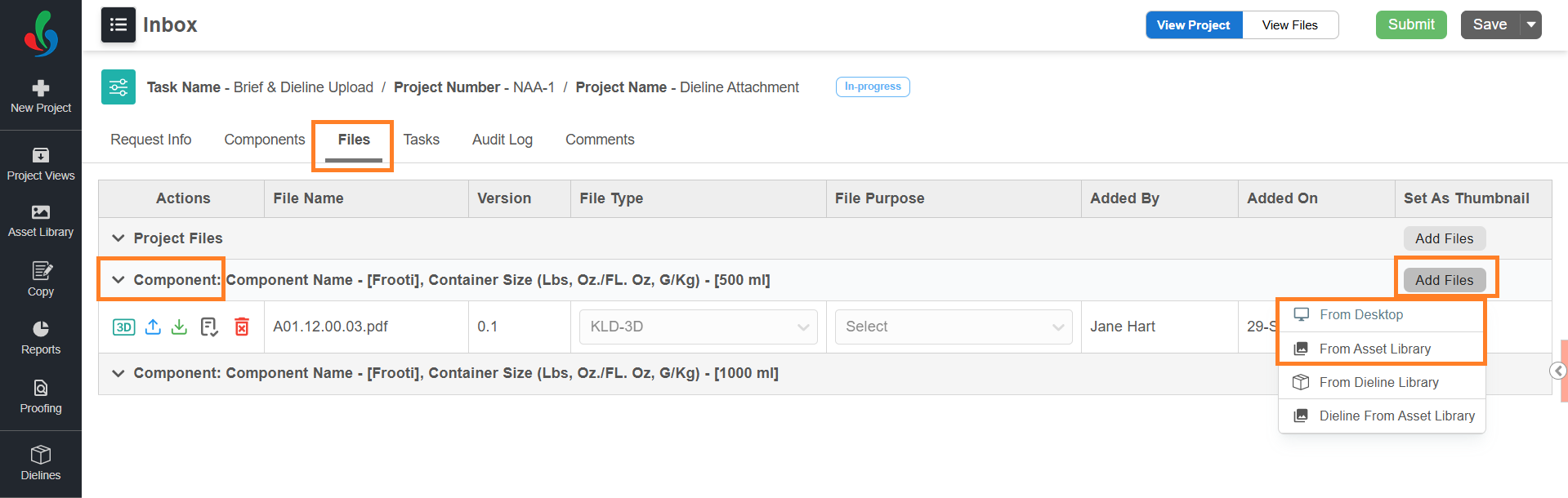
- Go to the Files tab of the project.
- Hover over the Add Files button next to the relevant component.
Note: A project must have at least one component to link a dieline. - Choose the source of the dieline: From Dieline Library or From Asset Library.
- Linking from the Dieline Library
- Select From Dieline Library.
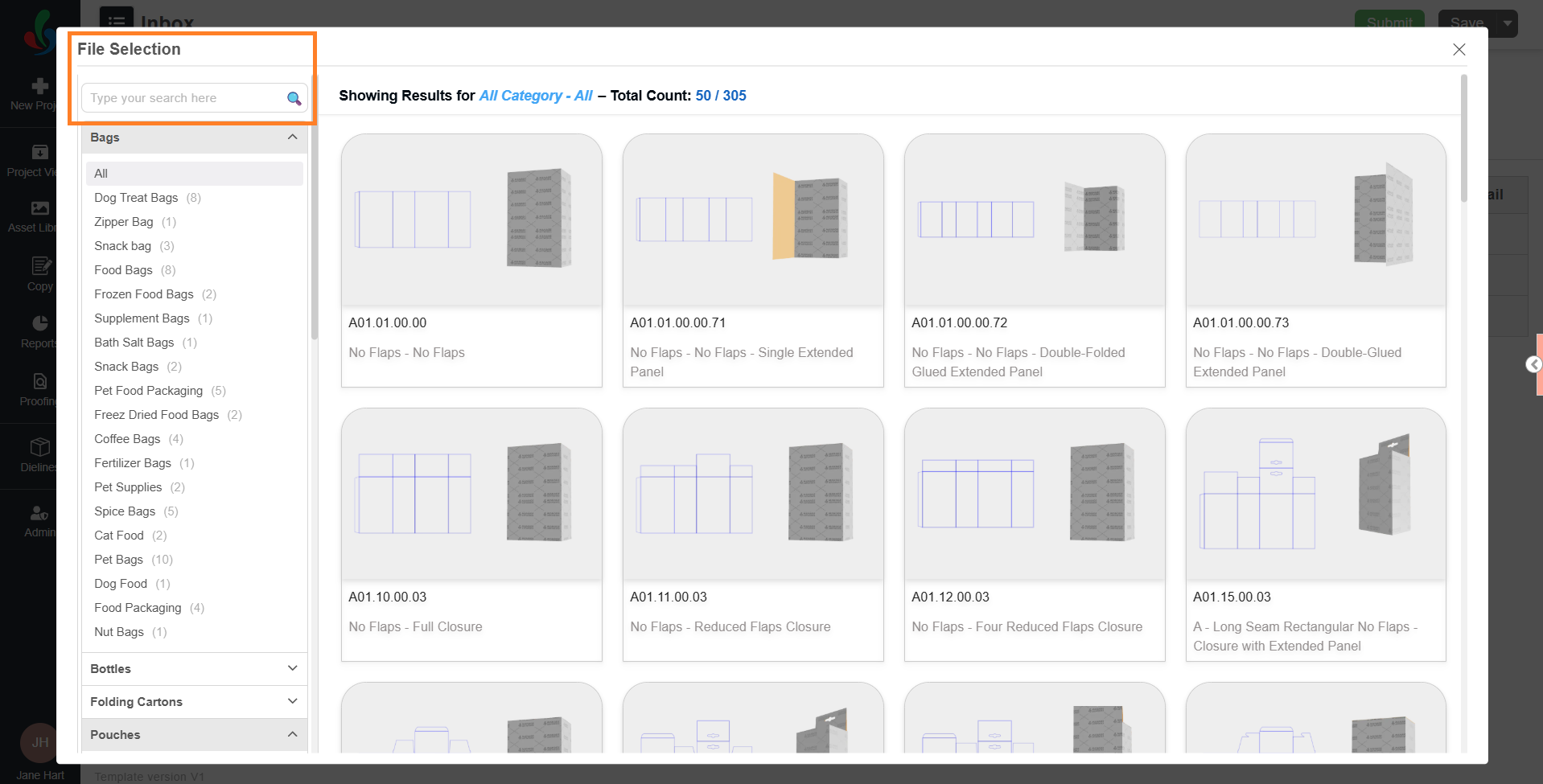
- In the File Selection pop-up:
- Browse through categories or use the search bar to locate a dieline template.
- Select a dieline to open the customization interface.
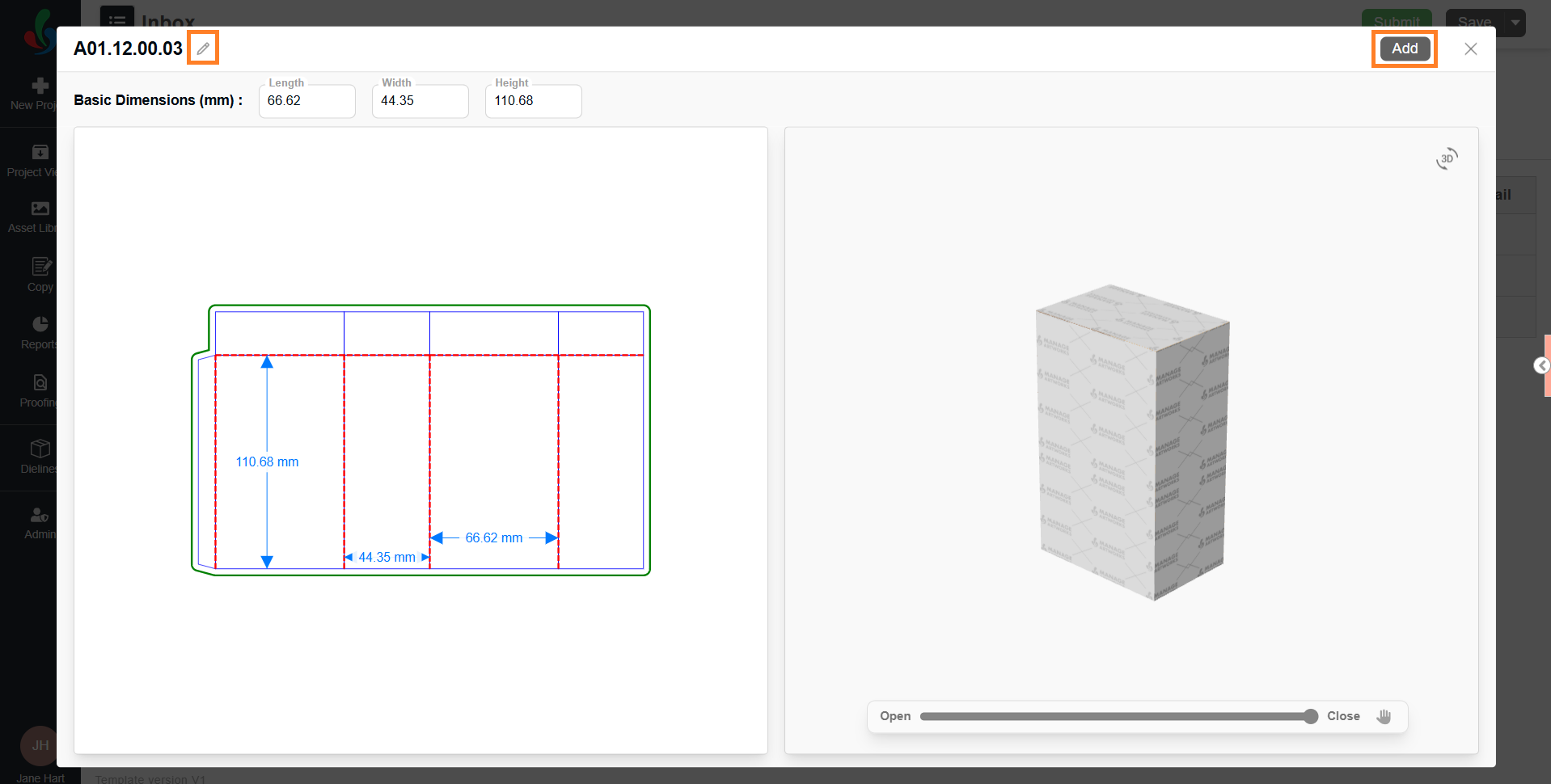
- In the customization screen:
- To rename the template, click the pencil (✏️) icon next to the current dieline title.
- Enter the desired name in the input field and press Enter to confirm.
Note: The dieline will be added to the project with this custom name. If the dieline is later published to the Asset Library, the same custom name will be retained and reflected there. - Customization options differ based on the selected dieline type. For more details on customization, refer to the Customization Options.
- Use the 3D preview and configuration tools to visualize and modify the dieline as desired.
- Once customized, select Add.
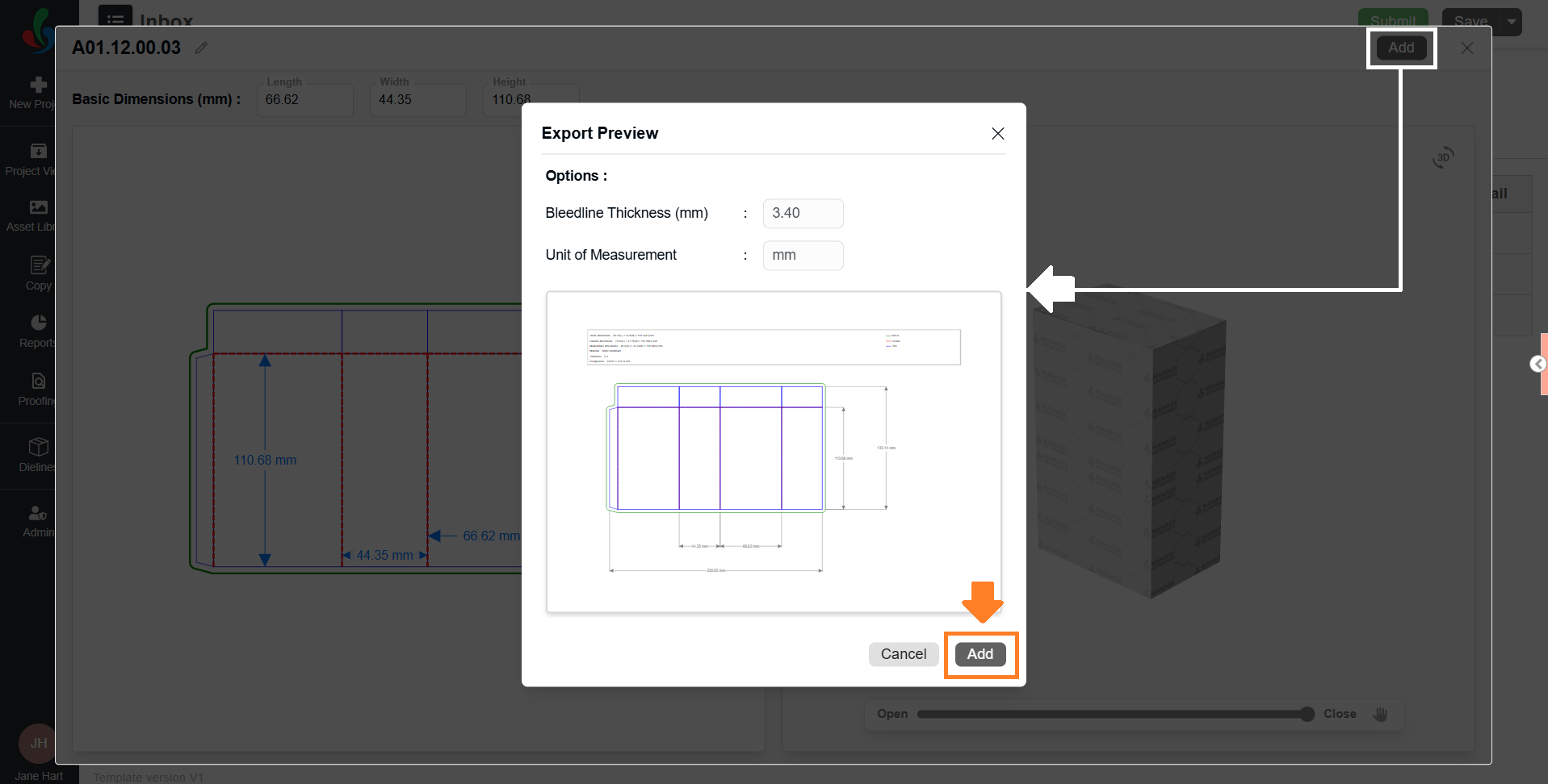
- An Add Preview dialog will appear:
- Bleed Measurement: This value is pre-filled based on the Admin settings. You can modify it if required.
- Measurement Scale (UOM): Pulled from Admin settings; this field is read-only.
Note: To modify the default Bleed Measurement or Unit of Measurement (UOM), refer to Dieline Parameter Configuration in the Admin module.
- Select Add to attach the customized dieline to the selected component.
Note: Only one dieline can be linked per component.
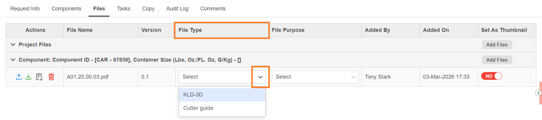
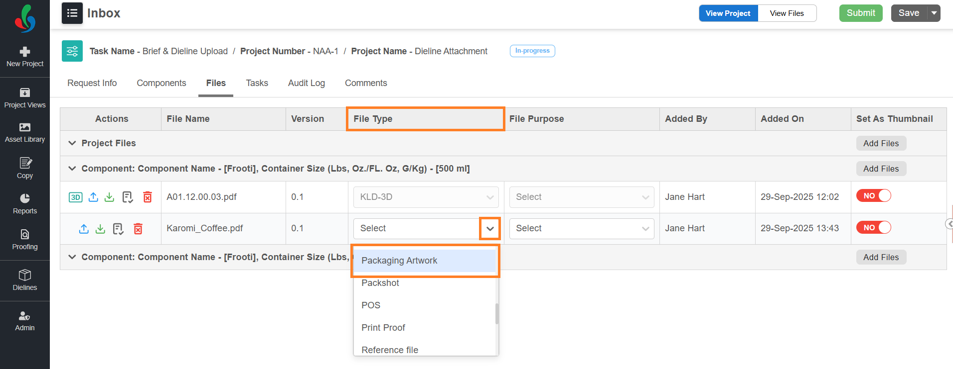
- After attaching the dieline, select the File Type drop-down corresponding to the attached file and choose the required file type from the list.
- The available file types are determined by the configuration in the Admin module. By default, only KLD-3D is set as an acceptable file type for dielines.
Note: To configure acceptable file or asset types for Dieline, refer to Dieline Parameter Configuration in the Admin module.
- Link a Dieline from Asset Library
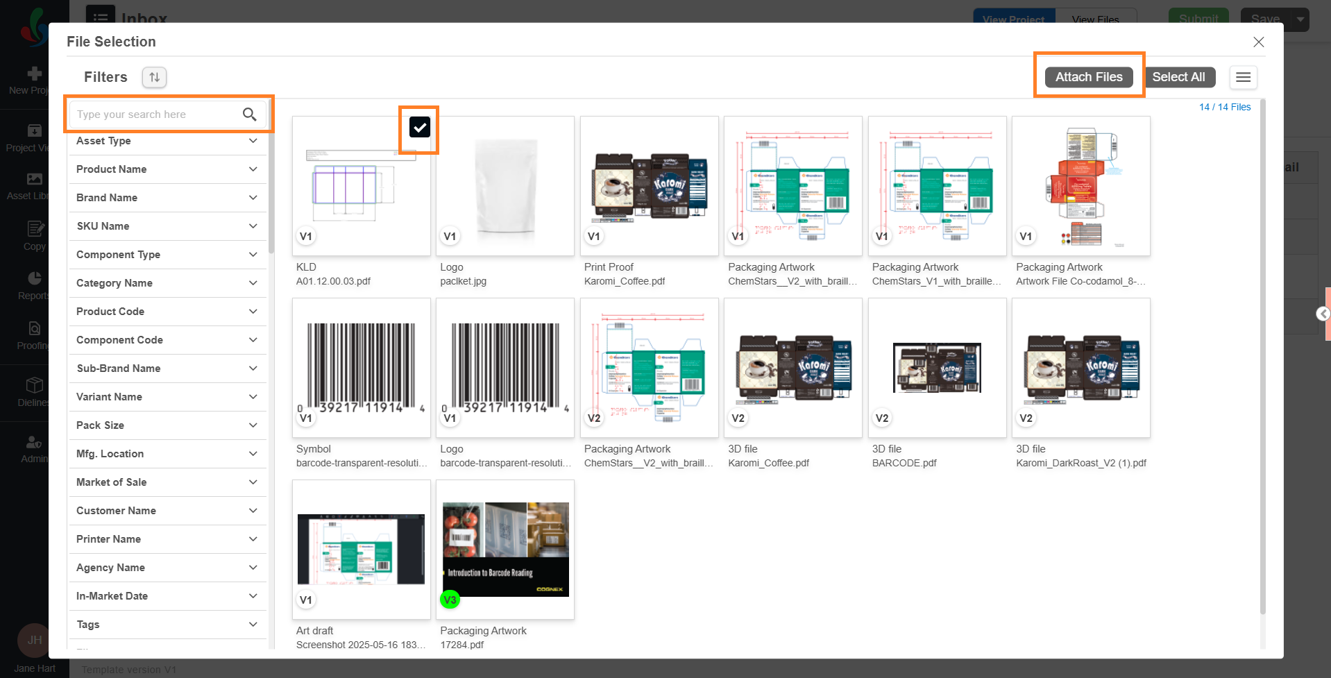
Note: Only published dielines from the Asset Library can be linked to a project. Customization is not allowed when using this method.- Select From Asset Library from the file source options.
- In the File Selection pop-up:
- Browse through categories or use the search bar to locate the dieline file.
- Select a published dieline or KLD to attach it to the selected component.
- Select Attach Files to complete the linking.
Note: When a dieline is added from the Asset Library, its file purpose is automatically set to Reference Only.
- Linking from the Dieline Library
03. Attach Packaging Artwork to a Dieline-Linked Component
Once the dieline is ready, you can download it as a PDF and use it as the base for creating packaging artwork in external applications such as Adobe Illustrator or InDesign. (For instructions on downloading, see Manage a Linked Dieline.)
When the artwork is ready, attach it to the same component as the dieline. This enables you to view and validate the packaging artwork in relation to the dieline.
| Note:
|
To attach the artwork to the component:
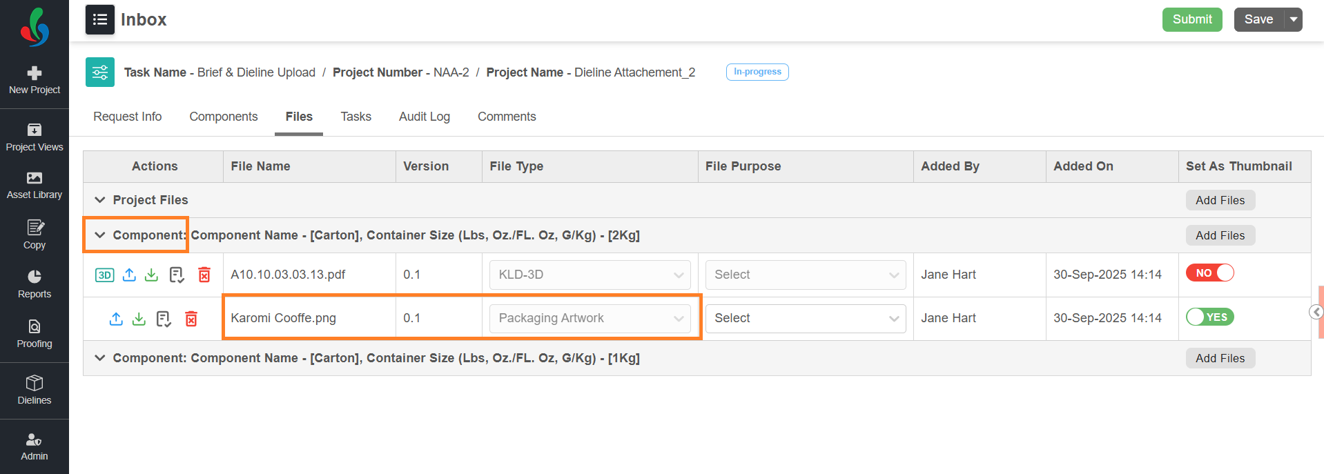
- Navigate to the Files tab.
- Hover over the Add Files button corresponding to the component.
- Select the file(s) using one of the following method:
- From Desktop: Allows you to browse and select files from your local system.
- Select From Desktop.
- Locate and select your artwork.
- Select Open.
- Asset Library: Select existing files from the Asset Library.
- Select From Asset Library.
- Choose the desired artwork from the File Selection window.
- Select Attach Files to add it to your component.
- From Desktop: Allows you to browse and select files from your local system.
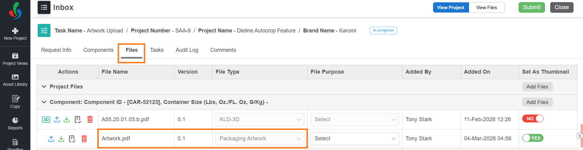
- After attaching the artwork file, select the File Type drop-down corresponding to the attached file and choose the required file type from the list.
Note: If the file is selected from the Asset Library, the File Type is auto-populated based on metadata and cannot be changed. - The available file types are determined by the configuration in the Admin module. By default, only Packaging Artwork is set as an acceptable file type for artworks.
Note: To configure acceptable file or asset types for Artwork, refer to Dieline Parameter Configuration in the Admin module.
- Once artwork is attached, proceed to Overlay Check.
04. Overlay Check
Once artwork is attached to a dieline-linked component, you cannot submit or proceed with the task until an Overlay Check is completed. This ensures that the linked dieline and the attached artwork are properly aligned.
| Overlay Check is required only when both of the following are attached to the same component:
The Overlay Check validation applies only to the file types that are configured as Dieline and Artwork in the Dieline Parameter Configuration section of the Admin module. |
 | Auto Crop works only when the artwork is based on a ManageArtworks-generated dieline PDF with intact embedded metadata. If the system detects that:
The following message is displayed: "Unsupported Dieline – Auto Crop may not work" In this case, Auto Crop will be disabled and you must use the Mark Region method. For Auto Crop, it is recommended to retain the default dieline layer name as “dieline”. If the layer name is changed, Auto Crop will still work, but manual configuration is required. |
You can perform the Overlay Check using one of the following methods:
- Auto Crop (Recommended)
- Mark Region (Manual method)
1. Perform Overlay Check Using Auto Crop
- Go to the Files tab.
- Select the artwork file attached to the dieline-linked component. The file opens in the Web Viewer.
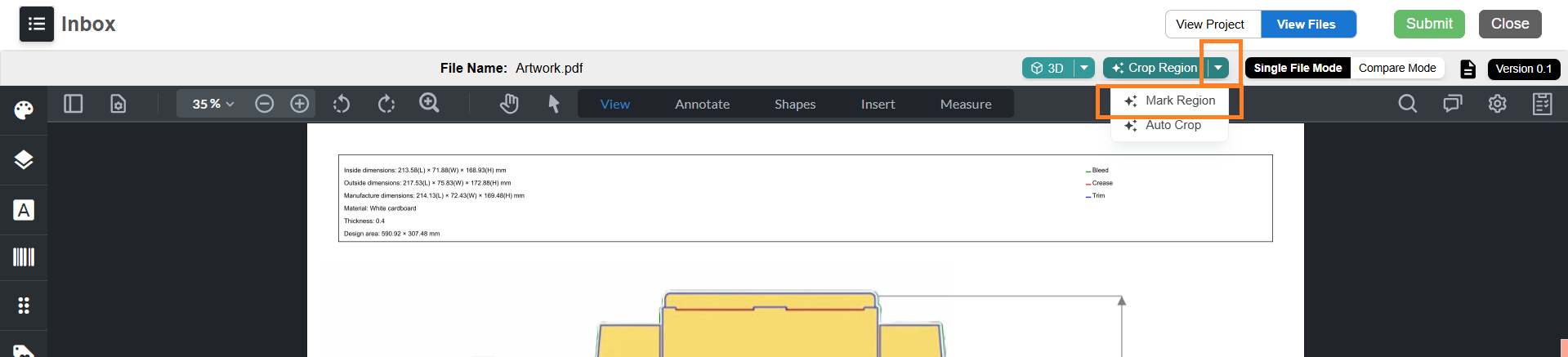
- Select the Crop Region drop-down menu.
- Select Auto Crop. The Artwork Crop Settings panel opens.
- Auto Detection Behavior:
- If the artwork is created using a ManageArtworks-generated dieline PDF and the embedded dieline metadata is intact:
- Auto Crop settings are automatically loaded from the dieline metadata.
- The following values are auto-selected:
- Target layer
- Dieline stroke color
- Dieline fill color
- Layers to remove (if applicable)
- If the dieline layer name has been modified:
- Auto Crop will still works.
- You must manually configure the Auto Crop settings (target layer, stroke, fill, etc.). Refer to Step f (Configure Artwork Crop Settings).
- If the artwork is based on a custom or third-party dieline, or if the ManageArtworks dieline metadata is missing:
- Auto Crop will not work.
- You must use the Mark Region option to perform Overlay check. Refer to Perform Overlay Check Using Mark Region.
- If the artwork is created using a ManageArtworks-generated dieline PDF and the embedded dieline metadata is intact:
- Configure Artwork Crop Settings
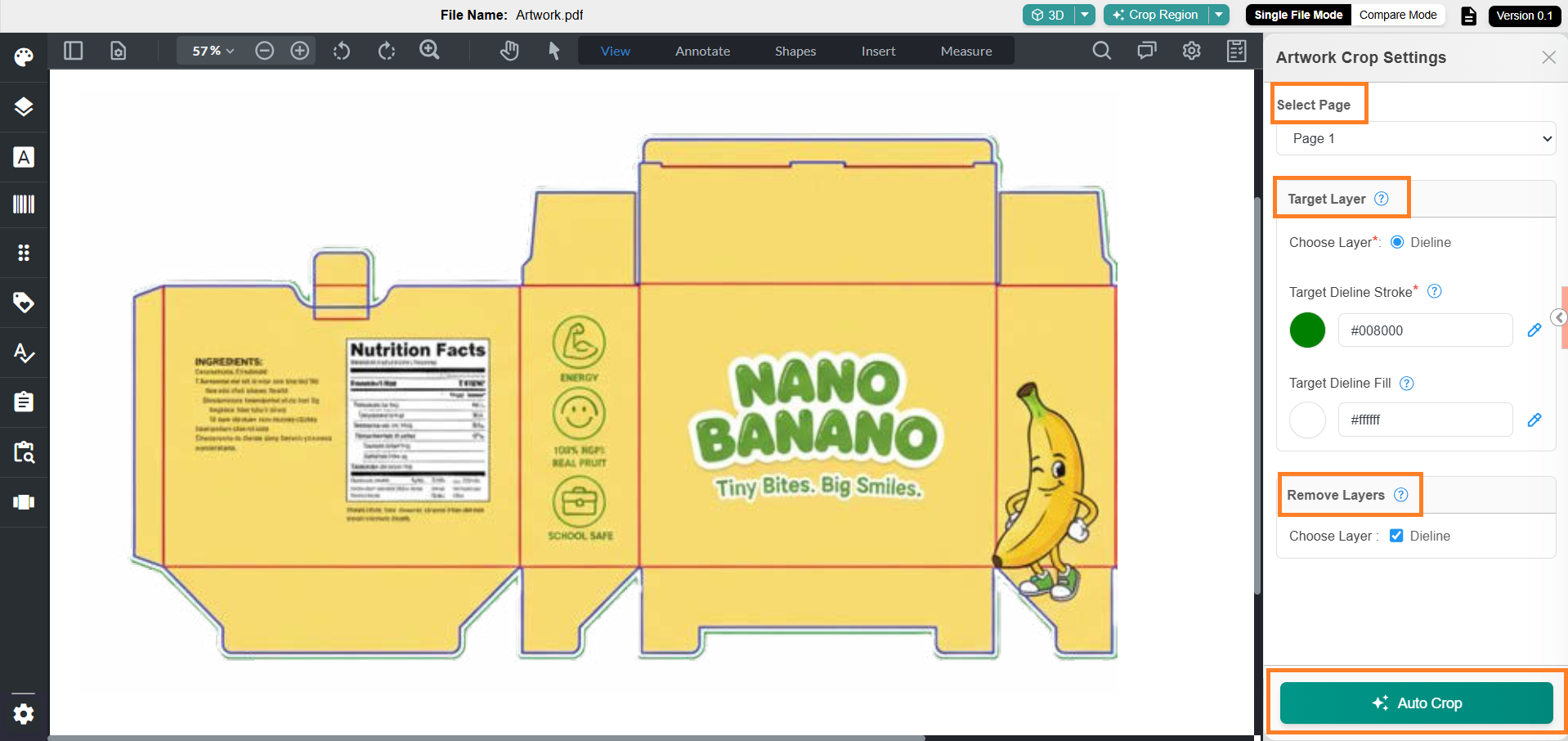
The Artwork Crop Settings panel contains three sections:- Select Page
Allows you to choose the page that contains the dieline to be cropped. For example, if the artwork file has 10 pages and the dieline is present on page 5, you can select Page 5 from the drop-down menu.
Note: When you select the dieline stroke, the corresponding page number is automatically selected by the system. Therefore, you do not need to manually choose the page. - Target Layer
Allows you to specify the layer containing the dieline. This section includes the following options:- Choose Layer: Lists all the layers associated with the artwork. Select the layer where the dieline is available.
Note: If the artwork has only one layer, only that layer will be available for selection. Select it. If the artwork does not contain any layers, no layers will be listed for selection. - Target Dieline Stroke: Enables you to select the stroke color of the dieline. This helps the system identify and crop the dieline accurately. You can either enter the hex code of the stroke color or use the color picker tool. You can select either the outer layer (Bleed Line) or the inner layer (Trim Line) of the dieline.
- If you select the outer layer (Bleed Line), you must also select the fill color when the dieline is system-generated.
- If the dieline is manually created or customized, selecting the fill depends on the creative setup — it is required only if the fill exists in the dieline layer.
Note: When using the color picker, zoom in closely to the dieline stroke for accurate selection.
- Target Dieline Fill: Allows you to specify the dieline fill color. Similar to the stroke option, you can enter the hex code or use the color picker tool. If you have selected the outer Bleed Line from a system-generated dieline, you must select the fill color (typically white) for Auto Crop to function correctly.
- All system-generated dieline bleed lines contain a fill layer; without selecting this fill, the Auto Crop process will not execute properly.
- If you have selected the inner Trim Line, or if the bleed line does not have a fill, selecting a fill color is not required.
- Choose Layer: Lists all the layers associated with the artwork. Select the layer where the dieline is available.
- Remove Layers
Allows you to remove unwanted layers from the cropping process. For example, you can exclude non-artwork layers such as dieline, measurement, or annotation layers, keeping only the artwork layer for cropping.
Note: If the artwork has only one layer, that layer will be available for selection — however, it should not be selected for removal. If the artwork does not contain any layers, no layers will be listed for selection.
- Select Page
- After configuring the settings (if required), select Auto Crop.
- The system crops the dieline region and opens the cropped area in the Upload & Design window.
- If required, adjust the overlay position using the bounding box controls.
- The Overlay Check is completed once the artwork is successfully overlaid on the dieline.
- You can now either proceed with task submission or explore the enhanced features available in the Web Viewer for artworks linked to a dieline. To explore the features, refer to 05. Enhanced Web Viewer (Dieline + Artwork Attached) step. If not required, you can skip this step and proceed to 06. Manage Linked Dieline or Packaging Artwork.

2. Perform Overlay Check Using Mark Region
- Go to the Files tab.
- Select the artwork file attached to the dieline-linked component. The file opens in the Web Viewer.
- Select the Crop Region drop-down menu.
- Select Mark Region.
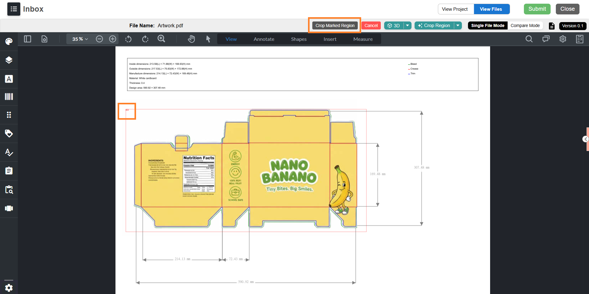
- Draw a selection over the area of the artwork you want to overlay.
Note: Typically, users mark the entire artwork area for overlay. However, the system allows marking any specific region. - Select Crop Marked Region.
- The selected area opens in the Upload & Design window overlaid on the dieline.
- Adjust the size and position of the overlay using the bounding box controls.
- Once the cropped region overlaid on the dieline, the validation is considered done.
- You can now either proceed with task submission or explore the enhanced features available in the Web Viewer for artworks linked to a dieline. To explore the features, refer to 05. Enhanced Web Viewer (Dieline + Artwork Attached) step. If not required, you can skip this step and proceed to 06. Manage Linked Dieline or Packaging Artwork.
05. Enhanced Web Viewer (Dieline + Artwork Attached)
When a packaging artwork is attached to a dieline-linked component, selecting the file opens it in the Web Viewer with enhanced capabilities.
The following features are available:
- Mark Region – Manually crop and extract a specific area of the artwork for overlay or simulation.
- Auto Crop – Automatically detect and crop the artwork based on the linked dieline.
- 3D View – View the artwork applied to the 3D structure with an interactive open/close slider.
- 3D Simulation – Open the Upload & Design window to customize and preview the dieline in 3D.
| Note: This is an optional step. You can explore these features for better visualization or skip this step and proceed with managing the linked dieline, artwork, or moving to the publish stage. The enhanced features are available only when you open a file type that is configured in the Dieline Parameter Configuration section of the Admin module. |
Mark Region Functionality
The Mark Region feature allows you to select specific areas of the artwork and overlay them on the dieline.
- In the Web Viewer, select the Crop Region drop-down menu.
- Select Mark Region.
- Draw a selection over the area of the artwork you want to overlay.
- Select Crop Marked Region.
- The cropped area opens in the Upload & Design window, overlaid on the dieline.
- Resize or reposition the overlay using the bounding box.
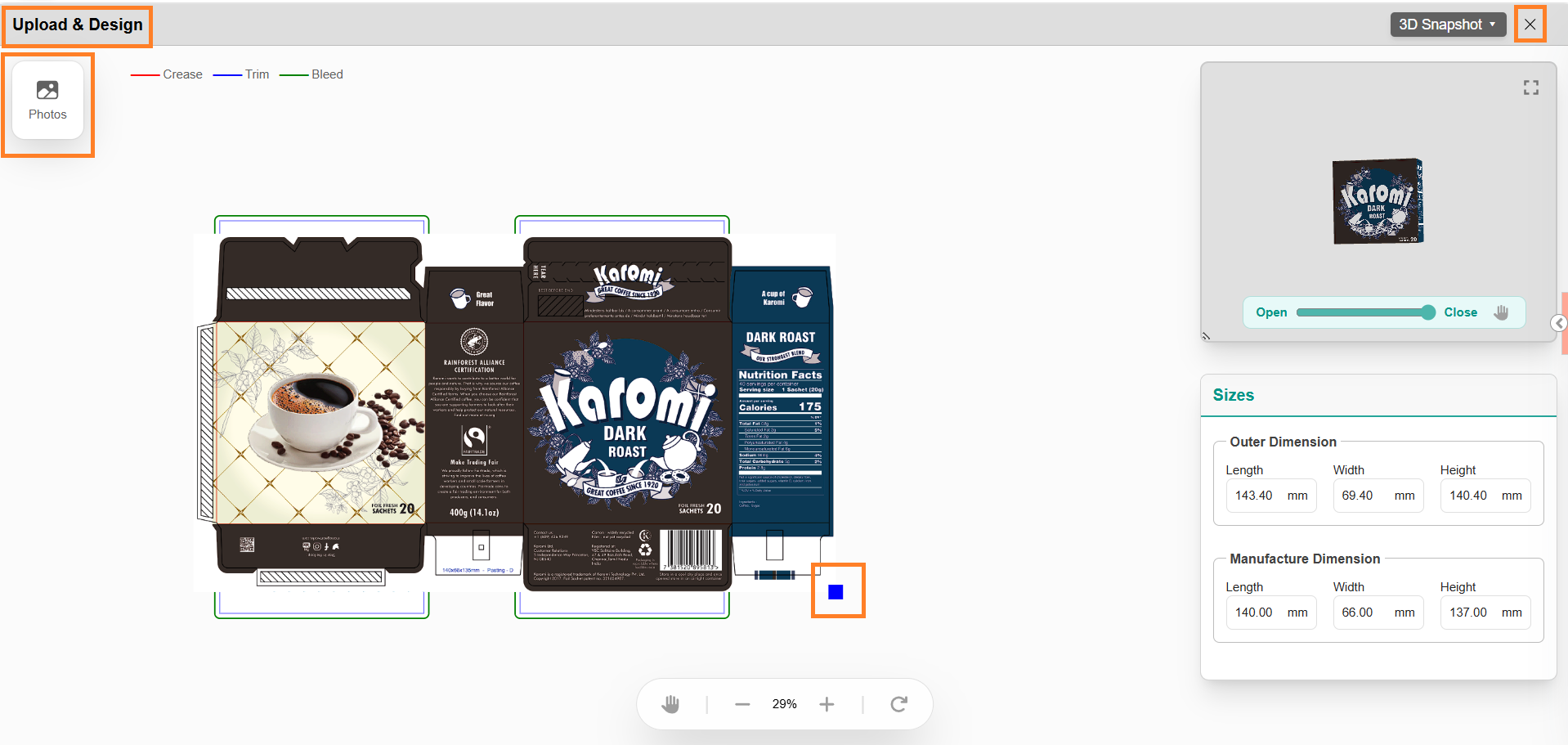
- To overlay more regions:
- Close the Upload & Design window.
- Repeat steps 1–5.
- To remove an overlaid image, select the Photos icon and clear the checkbox next to the image.
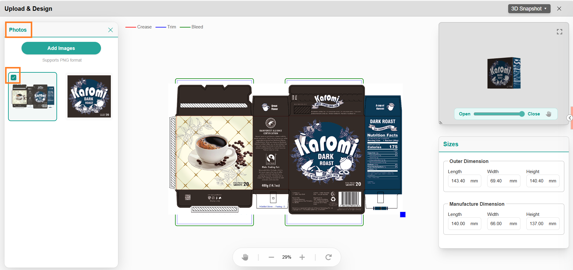
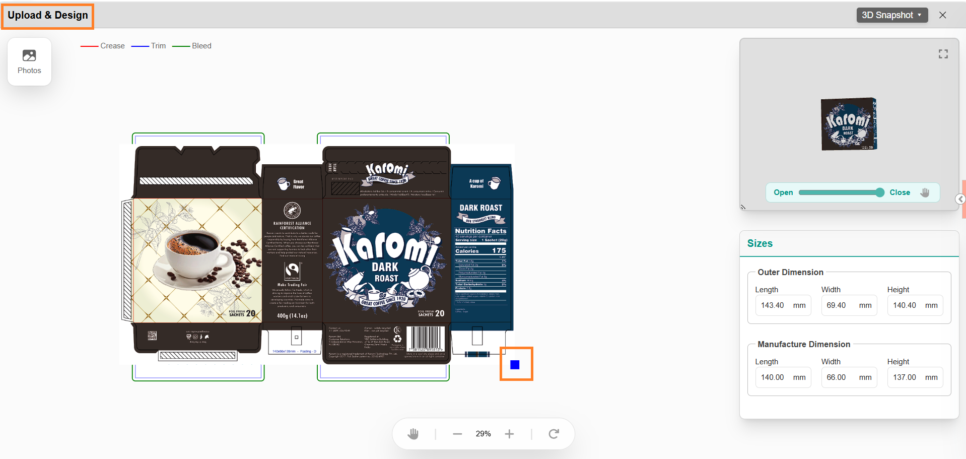
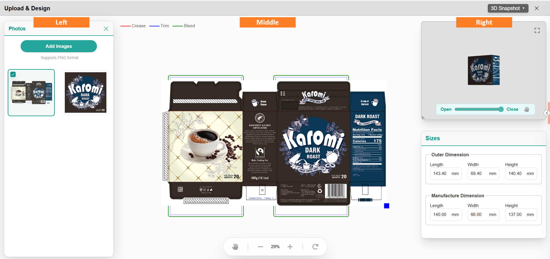
Upload & Design Window
The Upload & Design interface is split into three main sections:
Section | Functionality |
| Left: Image Uploads | Upload, manage, and select image files to overlay. |
| Middle: Dieline Editor | Position and align artwork or images over the dieline. |
| Right: 3D Preview & Controls | Visualize dieline in 3D with interaction features: - Slider for open/close simulation - Customization options only for appearance based on dieline type. Changing dimensions are not allowed |
Overlay External Images
You can also overlay external images (PNG format) that are not part of the packaging artwork.
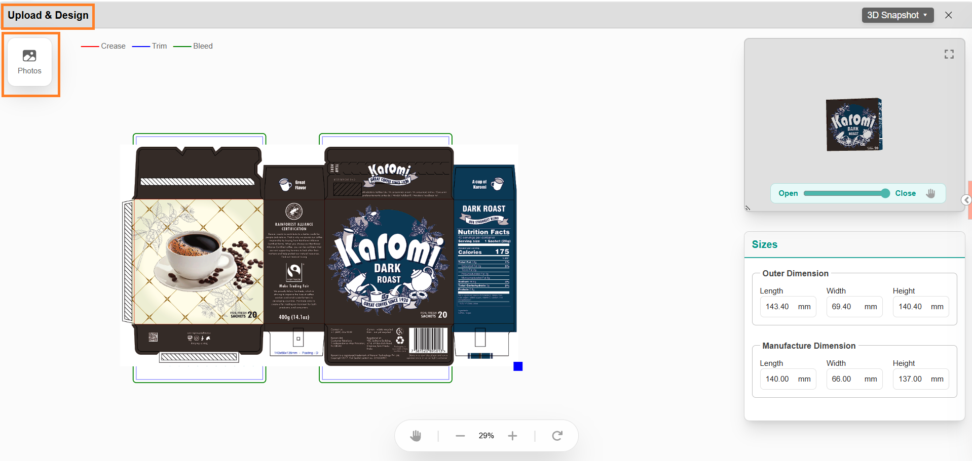
Steps:
- In the Upload & Design window, select Photos.
- In the left panel, select Add Images.
- Browse and select PNG files from your local system.
- Select Open to import.
- Select the uploaded image from the Photos panel.
- If required, drag, resize, and position the image on the dieline.
Note: Multiple external images can be overlaid if required.

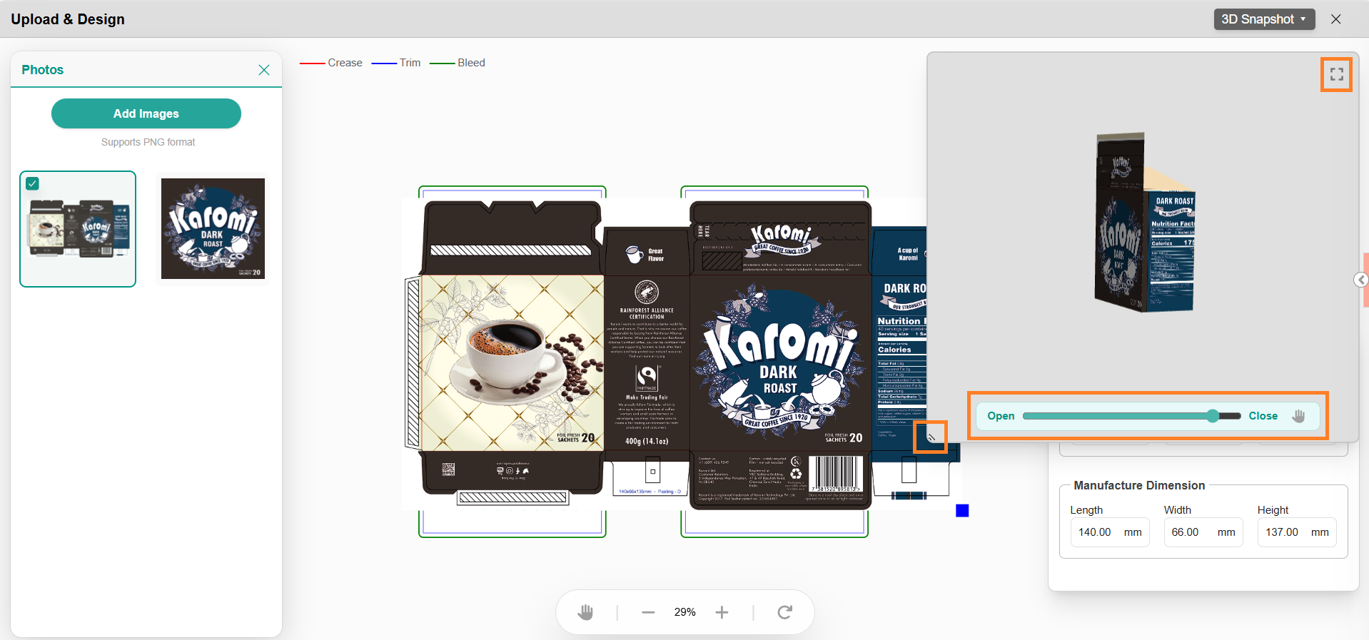
3D Simulation Controls
The 3D Preview panel provides a real-time visualization of dielines with applied overlays, allowing you to interactively explore the design.
- Resize the 3D View: Drag the bottom-left corner of the 3D panel to adjust its size.
- Simulate Opening and Closing: Use the interactive slider to preview the dieline in different open/close positions.
- Pan the View: Click the Pan icon to move the 3D model within the panel.
- Maximize the Panel: Click the Maximize icon in the top-right corner to expand the 3D preview to full size.
3D Snapshot
Use the 3D Snapshot option to capture images of the artwork applied to the 3D model.
To capture a snapshot:
- Select the 3D Snapshot button.
- Hover over the button to view the available options:
- Download Snapshot
- GS1 Profile Snapshot

Download Snapshot
- Select Download Snapshot to capture and save the current 3D view directly to your device.
- The system generates the snapshot based on the current camera position and automatically downloads it to your local system.
GS1 Profile Snapshot
The GS1 Profile Snapshot option enables users to generate GS1-compliant product images using predefined configuration profiles.
This feature:
- Automatically generates product images from the 3D model
- Applies GS1 standards for naming, metadata, and orientation
- Reduces manual effort and minimizes configuration errors
Unlike the standard snapshot, GS1 Profile Snapshot uses profile-based configuration to ensure consistency and compliance.
For detailed instructions, refer to GS1 Profile Snapshot.
Auto Crop Functionality
The Auto Crop feature automatically detects the dieline region and extracts the relevant artwork area for overlay or simulation. This functionality reduces manual effort and ensures accurate alignment between the artwork and the linked dieline.
Auto Crop is supported only when the artwork is created using a ManageArtworks-generated dieline PDF with intact embedded metadata.
If the required metadata is not available, Auto Crop will be disabled and you must use the Mark Region option instead.
To use Auto Crop:
- In the Web Viewer, select the Crop Region drop-down menu.
- Select Auto Crop.
- Configure the settings if required.
Note: For detailed configuration steps and supported scenarios, refer to Perform Overlay Check Using Auto Crop in the previous section. - Select Auto Crop to generate the overlay.
- Once the cropped region is overlaid successfully, the Overlay Check is considered complete.
3D Simulation Functionality
The 3D Simulation option allows you to open the Upload & Design window, where you can:
- Add overlays
- Adjust positioning
- Preview the dieline in 3D
To Access 3D Simulation
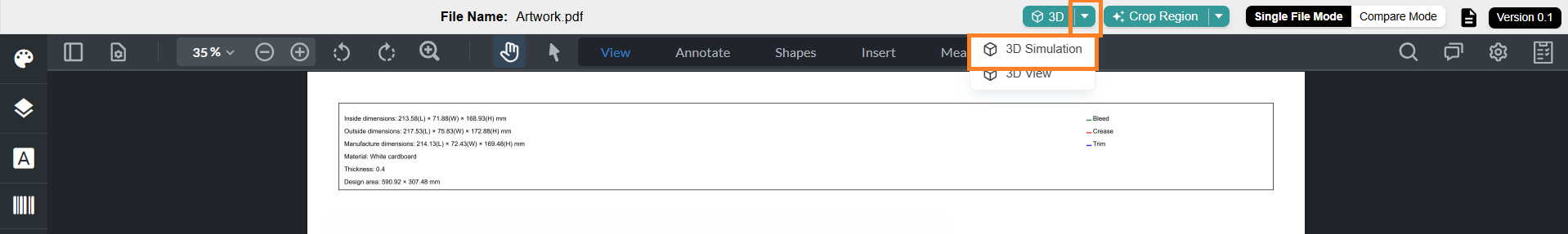
- In the Web Viewer, select the 3D drop-down menu.
- Select 3D Simulation.
- The Upload & Design window opens.
- Refer to Upload & Design Window for detailed instructions on how to use this feature.
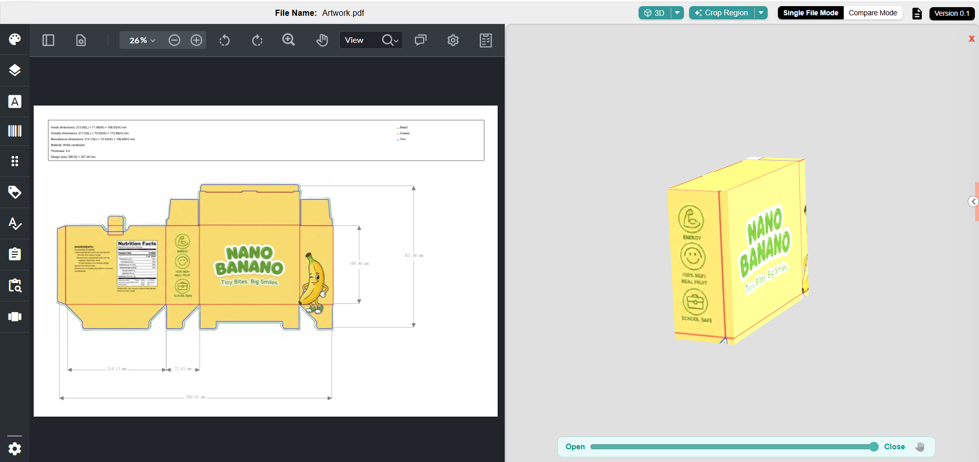
3D View Functionality
The 3D View option allows you to preview the artwork applied to the 3D structure.
| Note: This option is available only after the artwork has been successfully overlaid onto the 3D object. |
To Access 3D View:
- In the Web Viewer, select the 3D drop-down menu.
- Select 3D View.
- The 3D preview opens side-by-side within the viewer. Use the slider to simulate the structure from closed to open states.

06. Manage Linked Dieline or Packaging Artwork
Once a dieline or packaging artwork is linked to a project component, several management actions become available. You can use these options as needed or continue progressing with your project.
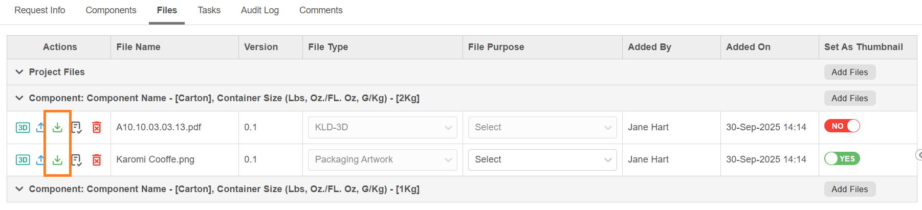
Download
- For Dieline: Select the download icon next to the dieline file to download it in PDF format.
- For Packaging Artwork: Select the download icon next to the artwork file to download it directly to your device.
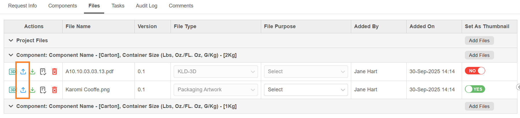
Update
- For Dieline:
- You can modify the existing dieline customization by selecting the Update button next to the linked file.
- This action opens the customization interface, where changes to dimensions or visual properties can be made based on the dieline type that you are working. For more details on customization, refer to the Customization Options.
- After making the desired adjustments, select Update. An Update Preview dialog will be displayed with the following details:
- Bleed Measurement: This value is pre-filled based on the Admin settings. You can modify it if required.
- Measurement Scale (UOM): Pulled from Admin settings; this field is read-only.
Note: To modify the default Bleed Measurement or Unit of Measurement (UOM), refer to Dieline Parameter Configuration in the Admin module.
- Select Update in the dialog to apply changes.
- Upon a successful update, the dieline version number is incremented automatically.
- For Packaging Artwork:
- Select the Update button next to the linked artwork file.
- Browse and select the updated file from your desktop (updates from Asset Library are not supported).
- Select Open to confirm.
- The file will be replaced with the new version, and the version number will increment automatically.
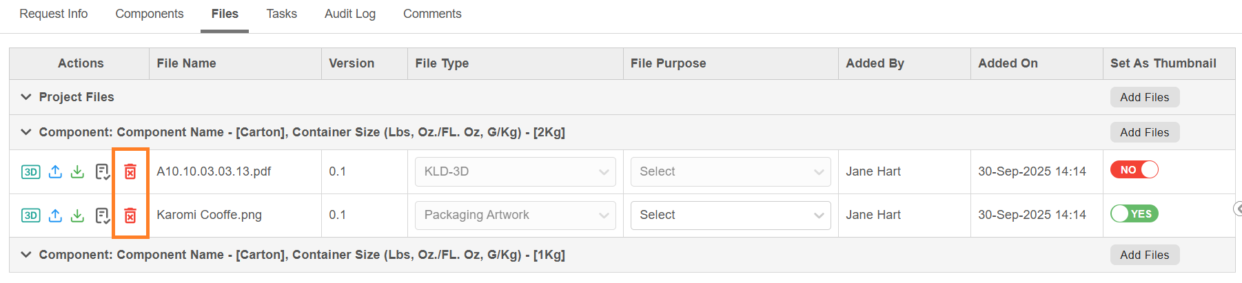
Delete
- For Dieline:
- A linked dieline cannot be deleted if it is already associated with an uploaded artwork (i.e., overlay check has been performed).
- To delete the dieline, the linked artwork must be removed first. Only then can the dieline be deleted from the Files tab.
- Select the Delete icon next to the dieline file, then confirm by selecting OK in the confirmation dialog.
- For Packaging Artwork:
- Select the Delete icon next to the artwork file.
- Confirm deletion by selecting OK in the confirmation dialog.
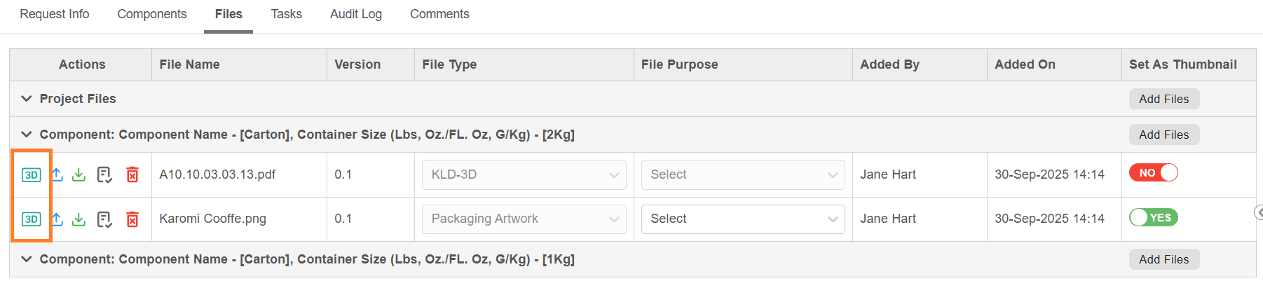
3D Preview
- For Dieline:
- Once the dieline is attached, a 3D Preview icon appears next to the KLD file in the Files tab.
- Selecting the dieline 3D icon opens an instant 2D and 3D preview of the dieline (without artwork overlay) directly within the Files tab—no need to open the full Web Viewer.
- For Packaging Artwork:
- Once the overlay is applied for an artwork, a 3D Preview icon appears next to the Packaging Artwork File in the Files tab.
- Selecting the artwork 3D icon opens a 3D preview of the dieline with the artwork overlaid, within the Files tab—no need to open the full Web Viewer.
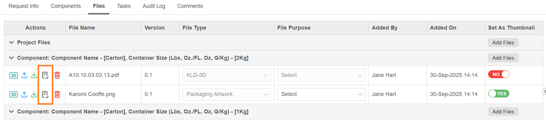
Viewer Checklist
- Select the Viewer Checklist icon to view checklist items associated with that file.
Note: The checklist items displayed depend on configuration parameters such as Task and Asset Type.
07. Publishing
Once the workflow is completed, files such as Dieline and Artwork are automatically published to the Asset Library, depending on the publish configuration.
| Note: To customize when and which file types should be published—such as after the completion of a specific task or upon workflow completion—please contact the ManageArtworks Support Team for assistance in setting up the appropriate configuration. |
| Note: If the dieline was added from the Asset Library, it is treated as a reference-only file and will not be re-published. |
| Key Points for Linking Dielines in a Workflow
|